Wednesday, August 18, 2010

Intro to Light Weight Vehicles- Senior Design Project

        My senior design project was to compete in a rudimentary car crash modeling also known as a crash cage competition with a partner.  The goal was to design a cage, which represented a car frame, that had to protect a passenger compartment from an initial crash impact and the engine after impact.  The passenger compartment was represented by a empty 6 cm by 6 cm box.  The engine was represented by a 6 cm by 6 cm solid box.  The crash was simulated by dropping the cage from about a 2 meter height with a weight on top of it.  The cage would slam into the ground, and the engineering design aspect of the project was to design it such that it crumpled in a way we desired, utilizing energy dissipation and crumple zones.

One of the crash cages I designed in SolidWorks.  
 The metal we used was aluminum and steel so knowing there mechanical properties were essential. We were only allowed to use cylindrical cuts and legs of the metal as shown in the model below.  It took many iterations to arrive at our final design.  We simulated the crash (drop) using by analyzing nodes in MatLab.  Using the mechanical properties such as elastic modulus, plasticity, and strength, we performed energy calculations to determine how our cage would deform after the impact.  Some of the results are displayed below.
MatLab Nodal Analysis of a part of the Cage.  Red is the original position of the nodes, and Blue is the deformed position. 
 After analysis showed sufficient energy dissipation in areas that we wanted to absorb energy, we took our SolidWork's model and built the crash cage cutting and drilling all the necessary pieces in the machine shop.
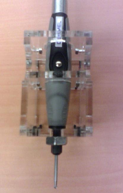
The fully assembled version of the crash cage.  
During the actual competition when we were dropping the cages, our two cage designs places 1st and 2nd.  Ours dissipated the most energy while keeping the passenger compartment safe.  It was a very fun event, made even funner by the fact that we came in first place.  We really spent our time analyzing the designs in MatLab to ensure our success.

Sunday, August 8, 2010

The Fab-@-Home Dremel Tool

Fab-@-Home is a student run team at Cornell University that has developed and now continues to build on a fabrication device (3D printer), which is cheap enough and simple enough to be built in a common house hold (Assuming a minimum technical background).  The 3D printer works like a regular printer in how the carriage moves around a page in the x-y plane while depositing ink.  The only difference is, in the 3D version it is no longer a plane but x-y-z space and instead of depositing ink, various materials are extruded onto the platform which can be built up layer by layer. 

The Model II version of the Fab-@-Home Printer
The uniqueness of the tool I designed for the printer is that it essentially does the reverse.  Instead of building up, the Dremel tool moves about the x-y-z coordinate system milling away at whatever material is already inside the printer. Depending on the Dremel and Dremel attachment used, a number of materials can be milled including, Styrofoam, soft woods (like balsa), and other soft materials like plastic and silicone.   

The SolidWorks Model of the Dremel Tool (Not the best image, but currently don't have access to SolidWorks)
The tool was designed and modeled in solid works.  It was then cut out of acrylic using a laser cutter.  
Assembled Dremel Tool
Below is a video of the tool in action. (After a few seconds you get the idea, and you can just jump around to see the finished result).  Enjoy!


Friday, August 6, 2010

Electro-Coalescence Effects on a Droplet at a Flat Interface


       This research was done in the Department of Mechanical and Aerospace Engineering at UCLA during the summer of 2007 in conjunction with the Summer Program for Undergraduate Research (SPUR).  It was done to determine if and how the presence of an electric field affects the coalescence of fluids. This research is useful in the petroleum industry where the separation of oil and water is crucial.  

       When dropping a water droplet through the oil to the body of water, it rest on a microscopic film of oil preventing it from merging with the rest of the water.  It could rest as a separate droplet for hours, days, or indefinitely.  The electric field alters and accelerates the process of merging. 
The Set Up for the Experiment

      The electric field is determined by the voltage applied to the brass plates and the height of the interface.  The Strength of the electric field is calculated by dividing the voltage by the distance, D between the top brass plate and the oil/water interface.  The two plates essentially constitute a capacitor where in the calculation for electric field strength is the same as that of a capacitor.    
Electric Field, E = Voltage/Distance 

Coalescence of a droplet producing a secondary droplet
      The electric field causes the primary droplets to coalesce and also leave behind a secondary droplet (or even a third sometimes).  The time of coalescence of the primary drop and the size and time of coalescence of the secondary drop varied inversely with the strength of the electric field.  The production of secondary drops is common to most liquid droplets coalescing with larger liquid bodies.  The unique discovery came when we discovered there was a threshold voltage with which, no secondary drop was created and the time it took the droplet to coalesce was minimal and hardly detectable even with a high-speed camera.  


Coalescence without producing a secondary droplet.


The high-speed camera was used to record these events which took only fractions of a second.  The footage of the phenomena were used to measure the size of the droplets and the duration of their coalescence.  

The Set Up including the High-Speed Camera.